
in part one we covered the mechanical connection of a motor shaft to a gearbox’s inputs haft, enabling the transfer for torque.
Here in part 2 we cover the actual matting of a electric motor to a gearbox.
Every vehicle manufacture uses they’re own bellhousing bolt pattern, with different backspacing, locating features, and orientations.
In order to mate two different bellhousing(motor side and gearbox side), we have to define the correct backspacing(for shaft clearance), locating features(dowel pins, hub centric, tapperd bolts, etc) and the bolt pattern.

Often times bolt patterns collide with one another. One solution is to design in undercuts and counter bores to allow bolts on ether side of the adapter plate to fit. This results in a a complicated, costly and wasteful billet (machined from one piece) adapter.
a more elegant approach is to make an assembly:
-motor adapter plate
-spacer (if needed)
-gearbox adapter plate
cost reduction: when designing an adapter plate, you start out with stock material. material comes in standard sizes. if the part is far off from the stock material, the more material has to be removed, which takes more time, produces more waste resulting in a higher cost part.
The multipart assembly approach allows each section to be as close to stock materials as possible, while maintain all the required features.
not only that but some parts in the assembly can be made in larger quantities, benefiting from economies of scale, such as our universal leaf motor adapter pates, and nema B-face spacers.
locating features:
Motors and gearbox’s uses different types of locating features to keep everything on center. these features are the known as the driving features. The accuracy of these features take priority over everything else.
for example:
- air cooled vw’s transaxle uses a inner lip on the gearbox to keep the motor on center, the bolts merely keep it mounted.

- leaf motor uses 2 dowel pins.
- Mitsubishi outlander rear motor uses a center ring to locate the gearbox
Ideally measuring required features of a motor or gearbox would be done in a metrology lab with a cmm machine. most machine shops do this via a probe on a CNC machine
measuring:
- level the matting face
- define top dead center (TDC)
- locate the center, ie where in input/output shaft is. this will be the reference coordinates (x=0, y=0)
- probe each hole and locating feature relative to center (0,0).
we end up with a table of numbers refenced to center like so:
x y
-4.34 -4.22
-3.223 -2.12
-0.785 -2.26
step 1: plotting coordinates
take the table of coordinates and and plot them in space:

Now we have bolt hole locations relative to center. make sure these plots are fixed in space and are fully defined.
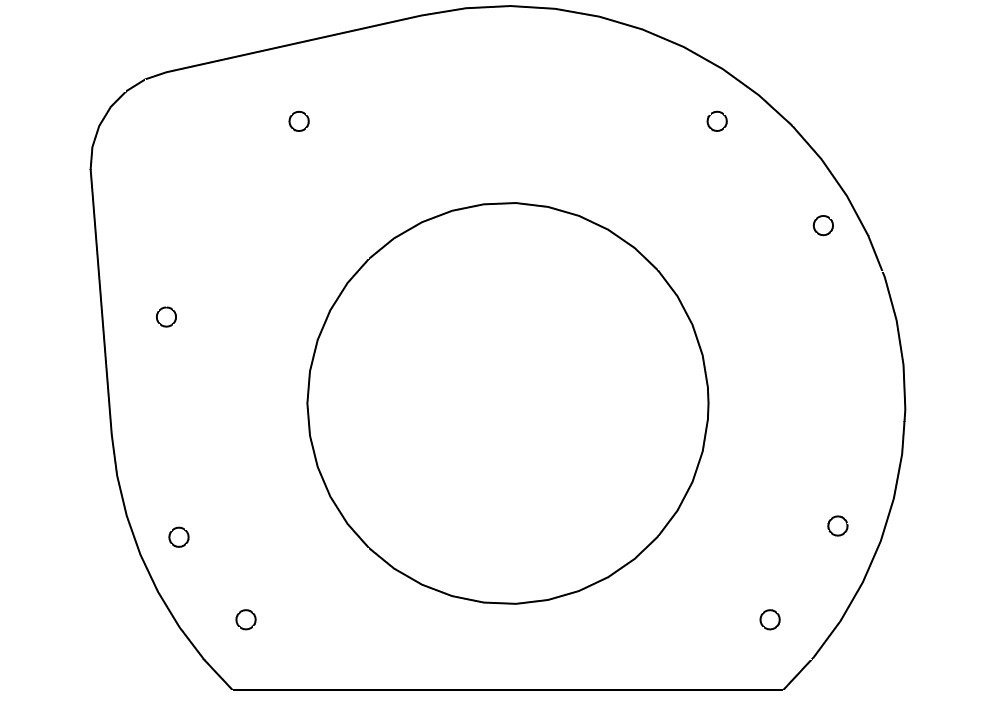
step 2: outline
Define the outline geometry. This should capture the full matting face of the part.
Start with a square or rectangle, what ever is closest to the bellhousing shape. With the Subaru gearbox, we’ll use a circle.

add in the odd features that persists (starter motor location, odd bolt hole, etc) :

bolt holes should have at minimum of 2x the thickness of the bolt in surrounding material:

Maintaining parallel and square lines is good practice as depending on how the part is made, some fixturing is required to hold the stock material in place during machining.
parallel lines make is easy to mount the part in a stock vise.
we’ve created a universal fixture, using the nema-b face pattern. As long as a part has the nema pattern, we can chuck it in the cnc machine at no added cost.
step 3: weight saving
lugging around extra material is a weight penalty, which effects range! every bit counts.
175mm bore works great, this is what all our adapter plates use.
step 4: universal bolt pattern
draw the nema B-face bolt pattern:
213.36mm diameter
4x 3/8-16 UNC holes 45 degrees from TDC:
For the transmission side, make these through holes. For the motor side make them threaded.

step 5: bolt holes
On motor side adapter plates, we uses counter sunk holes for the bolt pattern. This gives a completely flat face to work with:

in some cases some threaded holes are needed, such as the adapter plate for the outlander rear motor:

Step 6: back spacing
to find out the required backspacing, place a level on the matting face of the bellhousing and measure from the levels edge to the tip of the shaft.
this gives us the shaft-to-face length.
Some gearbox’s will have a reassessed shaft, so the shaft-to-face number will be negative.
Add the gearbox and motor shaft-to-face lengths together + 2mm for clearance.
this gives use the required backing spacing.
adapter thickness:
generally the motor plate should be made the thickest. our plates are 17mm thick, this enables threaded features to be placed on the adapter. Such as the NEMA B-face bolt pattern.
With the leaf to ea81 Subaru adapter, no additional spacer was needed. The 6mm gearbox plate and the 17mm leaf motor plate gave us the required backspacing of 23mm.
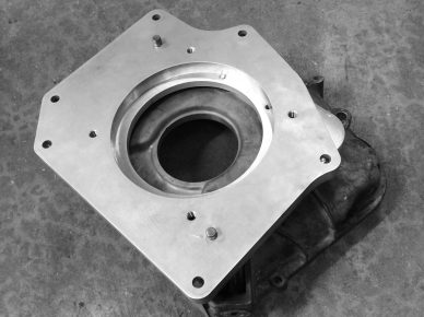
mated to the subaru bellhousing
Where as the leaf to Vw kit need a lot more, 60mm of spacing. so the 25mm nema B-face spacer was used:

(vw plate, nema spacer, leaf plate)
Step 7: Assembly
Its critical that the motor and gearbox shafts line up correctly, if they don’t there might be added stress on the bearings in ways the bearings where not designed for. This may lead to premature failure, either on the motor or the gearbox end.
One process that really helps remove this possibly (after accurately designing the adapter plate) is to assemble the motor, adapter plate, and gearbox in a vertical stack.
With the bolts on the motor and gearbox loose enough for some slight movement.

Spin the motor up slowly, this will help center the gearbox and motor with each other.
once spun a few times, the assembly should have settled itself.
In a alternating star pattern, bolt down the motor and gearbox in stages. i.e. don’t tighten one bolt all the way down. Tighten each bolt a little bit, move on to the next and keep repeating the pattern in till each bolt is tighten to the desired torque setting.
In part 2B we will cover making an adapter plate by hand. A lot of a the same processes still applies, but there are some tricks to make it easier and what to look out for.
Leave a Reply